To meet recent market demand change i.e. less inventory with variety of products, system has been changed accordingly to short run production form mass production.
In press room, products lot size is now 500-2,000 pcs / lot and die change requirement is 7 times / day, changed from 5,000-8,000 pcs / lot with 1 time / day die change
To achieve these production efficiency i.e. keeping high productivity against frequent die change requirement, quick die change system is greatly demanded by press users.
Here is one of obtainable examples, which shows so-called “Single Minute Die Change System”, adopted in car industry area.
This system consists of two (2) sets of moving bolster with upper die clamps as minimum requirement.
In addition to them, following new technologies or system should be adopted to achieve “Single Minute Die Change".
Thanks to these improved or developed systems, single minute die change can be carried out and is now proved with Komatsu Press in several industry area, such as car and appliance.
Komatsu is refining its technology to meet market demand, not only in the press area but also in the material handling area such as destacker, transfer system and palletizing system as “Total Single Minute Production Change” for Just in time production.
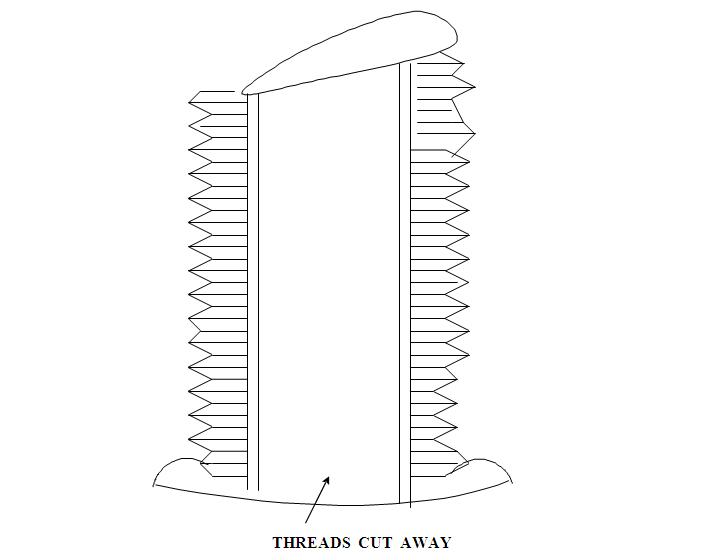
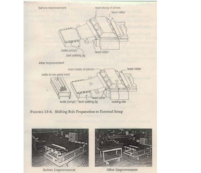
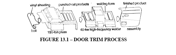
FIGURE 13.4 - SHIFTING BOLT PREPARATION TO EXTERNAL SET UP
FIGURE 13. 1 - BOLT PREPARATION TO BE INSERTED
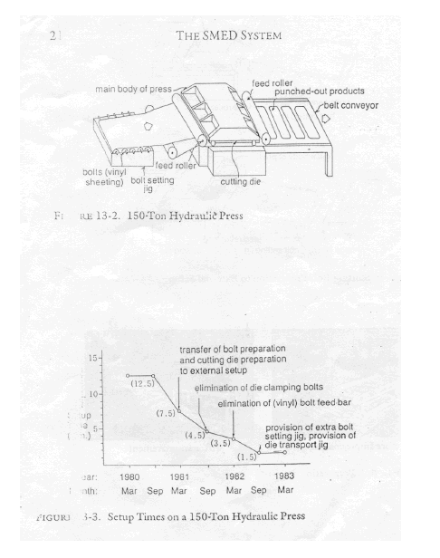
THE SMED SYSTEM
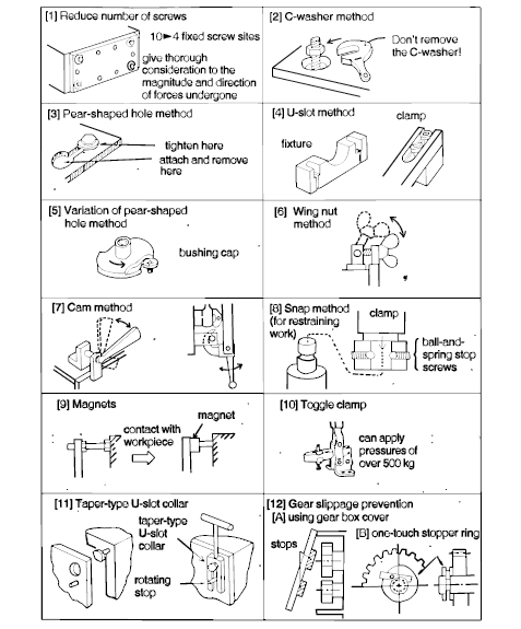
FIGURE 11.1 EXAMPLES OF SCREW