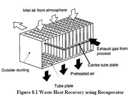
In a recuperator, heat exchange takes place between the flue gases and the air through metallic or ceramic walls. Duct or tubes carry the air for combustion to be pre-heated, the other side contains the waste heat stream. A recuperator for recovering waste heat from flue gases is shown in Figure 8.1.
The simplest configuration for a recuperator is the metallic radiation recuperator, which consists of two concentric lengths of metal tubing as shown in Figure 8.2. The inner tube carries the hot exhaust gases while the external annulus carries the combustion air from the atmosphere to the air inlets of the furnace burners. The hot gases are cooled by the incoming combustion air which now carries additional energy into the combustion chamber. This is energy which does not have to be supplied by the fuel; consequently, less fuel is burned for a given furnace loading.
Figure 8.2 Metallic Radiation Recuperator
The saving in fuel also means a decrease in combustion air and therefore stack losses are decreased not only by lowering the stack gas temperatures but also by discharging smaller quantities of exhaust gas. The radiation recuperator gets its name from the fact that a substantial portion of the heat transfer from the hot gases to the surface of the inner tube takes place by radiative heat transfer. The cold air in the annuals, however, is almost transparent to infrared radiation so that only convection heat transfer takes place to the incoming air. As shown in the diagram, the two gas flows are usually parallel, although the configuration would be simpler and the heat transfer more efficient if the flows were opposed in direction (or counterflow). The reason for the use of parallel flow is that recuperators frequently serve the additional function of cooling the duct carrying away the exhaust gases and consequently extending its service life.
Second common configuration for recuperators is called the tube type or convective recuperator.
The hot gases are carried through a number of parallel small diameter tubes, while the incoming air to be heated enters a shell surrounding the tubes and passes over the hot tubes one or more times in a direction normal to their axes
If the tubes are baffled to allow the gas to pass over them twice, the heat exchanger is termed a two-pass recuperator; if two baffles are used, a three-pass recuperator, etc. Although baffling increases both the cost of the exchanger and the pressure drop in the combustion air path, it increases the effectiveness of heat exchange. Shell and tube type recuperators are generally more compact and have a higher effectiveness than radiation recuperators, because of the larger heat transfer area made possible through the use of multiple tubes and multiple passes of the gases.
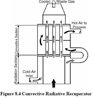
For maximum effectiveness of heat transfer, combinations of radiation and convective designs are used, with the high-temperature radiation recuperator being first followed by convection type.
These are more expensive than simple metallic radiation recuperators, but are less bulky. A Convective/radiative Hybrid recuperator is shown in Figure 8.4
The principal limitation on the heat recovery of metal recuperators is the reduced life of the liner at inlet temperatures exceeding 1100oC. In order to overcome the temperature limitations of metal recuperators, ceramic tube recuperators have been developed whose materials allow operation on the gas side to 1550oC and on the preheated air side to 815oC on a more or less practical basis. Early ceramic recuperators were built of tile and joined with furnace cement, and thermal cycling caused cracking of joints and rapid deterioration of the tubes. Later developments introduced various kinds of short silicon carbide tubes which can be joined by flexible seals located in the air headers.
Earlier designs had experienced leakage rates from 8 to 60 percent. The new designs are reported to last two years with air preheat temperatures as high as 700oC, with much lower leakage rates.
The Regeneration which is preferable for large capacities has been very widely used in glass and steel melting furnaces. Important relations exist between the size of the regenerator, time between reversals, thickness of brick, conductivity of brick and heat storage ratio of the brick.
In a regenerator, the time between the reversals is an important aspect. Long periods would mean higher thermal storage and hence higher cost. Also long periods of reversal result in lower average temperature of preheat and consequently reduce fuel economy. (Refer Figure 8.5).
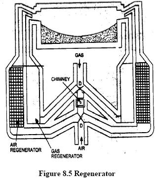
Accumulation of dust and slagging on the surfaces reduce efficiency of the heat transfer as the furnace becomes old. Heat losses from the walls of the regenerator and air in leaks during the gas period and out-leaks during air period also reduces the heat transfer.
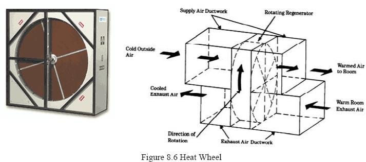
A heat wheel is finding increasing applications in low to medium temperature waste heat recovery systems. Figure 8.6 is a sketch illustrating the application of a heat wheel.
It is a sizable porous disk, fabricated with material having a fairly high heat capacity, which rotates between two side-by-side ducts: one a cold gas duct, the other a hot gas duct. The axis of the disk is located parallel to, and on the partition between, the two ducts. As the disk slowly rotates, sensible heat (moisture that contains latent heat) is transferred to the disk by the hot air and, as the disk rotates, from the disk to the cold air. The overall efficiency of sensible heat transfer for this kind of regenerator can be as high as 85 percent. Heat wheels have been built as large as 21 metres in diameter with air capacities up to 1130 m3/ min.
A variation of the Heat Wheel is the rotary regenerator where the matrix is in a cylinder rotating across the waste gas and air streams. The heat or energy recovery wheel is a rotary gas heat regenerator, which can transfer heat from exhaust to incoming gases. Its main area of application is where heat exchange between large masses of air having small temperature differences is required. Heating and ventilation systems and recovery of heat from dryer exhaust air are typical applications.
A heat pipe can transfer up to 100 times more thermal energy than copper, the best known conductor. In other words, heat pipe is a thermal energy absorbing and transferring system and have no moving parts and hence require minimum maintenance.
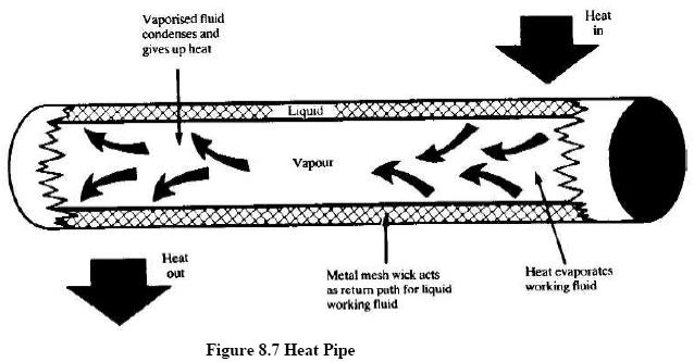
The Heat Pipe comprises of three elements – a sealed container, a capillary wick structure and a working fluid. The capillary wick structure is integrally fabricated into the interior surface of the container tube and sealed under vacuum. Thermal energy applied to the external surface of the heat pipe is in equilibrium with its own vapour as the container tube is sealed under vacuum. Thermal energy applied to the external surface of the heat pipe causes the working fluid near the surface to evaporate instantaneously. Vapour thus formed absorbs the latent heat of vapourisation and this part of the heat pipe becomes an evaporator region. The vapour then travels to the other end the pipe where the thermal energy is removed causing the vapour to condense into liquid again, thereby giving up the latent heat of the condensation. This part of the heat pipe works as the condenser region. The condensed liquid then flows back to the evaporated region. A figure of Heat pipe is shown in Figure 8.7
Performance and Advantage
The heat pipe exchanger (HPHE) is a lightweight compact heat recovery system. It virtually does not need mechanical maintenance, as there are no moving parts to wear out. It does not need input power for its operation and is free from cooling water and lubrication systems. It also lowers the fan horsepower requirement and increases the overall thermal efficiency of the system. The heat pipe heat recovery systems are capable of operating at 315oC. with 60% to 80% heat recovery capability.
Typical Application
The heat pipes are used in following industrial applications:
Cooling: Heat pipe heat exchangers precools the building make up air in summer and thus reduces the total tons of refrigeration, apart from the operational saving of the cooling system. Thermal energy is supply recovered from the cool exhaust and transferred to the hot supply make up air.
Heating: The above process is reversed during winter to preheat the make up air.
The other applications in industries are:
In case of boiler system, economizer can be provided to utilize the flue gas heat for pre-heating the boiler feed water. On the other hand, in an air pre-heater, the waste heat is used to heat combustion air. In both the cases, there is a corresponding reduction in the fuel requirements of the boiler. A economizer is shown in Figure 8.8.
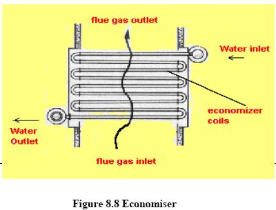
For every 220C reduction in flue gas temperature by passing through an economiser or a pre-heater, there is 1% saving of fuel in the boiler. In other words, for every 60C rise in feed water temperature through an economiser, or 200C rise in combustion air temperature through an air pre-heater, there is 1% saving of fuel in the boiler.
When the medium containing waste heat is a liquid or a vapor which heats another liquid, then the shell and tube heat exchanger must be used since both paths must be sealed to contain the pressures of their respective fluids. The shell contains the tube bundle, and usually internal baffles, to direct the fluid in the shell over the tubes in multiple passes. The shell is inherently weaker than the tubes so that the higher-pressure fluid is circulated in the tubes while the lower pressure fluid flows through the shell. When a vapor contains the waste heat, it usually condenses, giving up its latent heat to the liquid being heated. In this application, the vapor is almost invariably contained within the shell. If the reverse is attempted, the condensation of vapors within small diameter parallel tubes causes flow instabilities. Tube and shell heat exchangers are available in a wide range of standard sizes with many combinations of materials for the tubes and shells. A shell and tube heat exchanger is illustrated in Figure 8.9.
Figure 8.9 Shell & Tube Heat Exchanger
Typical applications of shell and tube heat exchangers include heating liquids with the heat contained by condensates from refrigeration and air-conditioning systems; condensate from process steam; coolants from furnace doors, grates, and pipe supports; coolants from engines, air compressors, bearings, and lubricants; and the condensates from distillation processes.
The cost of heat exchange surfaces is a major cost factor when the temperature differences are not large. One way of meeting this problem is the plate type heat exchanger, which consists of a series of separate parallel plates forming thin flow pass. Each plate is separated from the next by gaskets and the hot stream passes in parallel through alternative plates whilst the liquid to be heated passes in parallel between the hot plates. To improve heat transfer the plates are corrugated.
Hot liquid passing through a bottom port in the head is permitted to pass upwards between every second plate while cold liquid at the top of the head is permitted to pass downwards between the odd plates. When the directions of hot & cold fluids are opposite, the arrangement is described as counter current. A plate heat exchanger is shown in Figure 8.10.
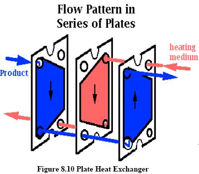
Typical industrial applications are:
It is quite similar in principle to the heat pipe exchanger. The heat from hot fluid is transferred to the colder fluid via an intermediate fluid known as the Heat Transfer Fluid. One coil of this closed loop is installed in the hot stream while the other is in the cold stream. Circulation of this fluid is maintained by means of la circulating pump.
It is more useful when the hot land cold fluids are located far away from each other and are not easily accessible.
Typical industrial applications are heat recovery from ventilation, air conditioning and low temperature heat recovery.
Waste heat boilers are ordinarily water tube boilers in which the hot exhaust gases from gas turbines, incinerators, etc., pass over a number of parallel tubes containing water. The water is vaporized in the tubes and collected in a steam drum from which it is drawn off for use as heating or processing steam.
Because the exhaust gases are usually in the medium temperature range and in order to conserve space, a more compact boiler can be produced if the water tubes are finned in order to increase the effective heat transfer area on the gas side. The Figure 8.11 shows a mud drum, a set of tubes over which the hot gases make a double pass, and a steam drum which collects the steam generated above the water surface. The pressure at which the steam is generated and the rate of steam production depends on the temperature of waste heat. The pressure of a pure vapor in the presence of its liquid is a function of the temperature of the liquid from which it is evaporated. The steam tables tabulate this relationship between saturation pressure and temperature. If the waste heat in the exhaust gases is insufficient for generating the required amount of process steam, auxiliary burners which burn fuel in the waste heat boiler or an after-burner in the exhaust gases flue are added. Waste heat boilers are built in capacities from 25 m3 almost 30,000 m3/ min. of exhaust gas.

Typical applications of waste heat boilers are to recover energy from the exhausts of gas turbines, reciprocating engines, incinerators, and furnaces.
In the various commercial options previously discussed, we find waste heat being transferred from a hot fluid to a fluid at a lower temperature. Heat must flow spontaneously “downhill”, that is from a system at high temperature to one at a lower temperature. When energy is repeatedly transferred or transformed, it becomes less and less available for use. Eventually that energy has such low intensity (resides in a medium at such low temperature) that it is no longer available at all to perform a useful function.
It has been taken as a general rule of thumb in industrial operations that fluids with temperatures less than 120oC (or, better, 150oC to provide a safe margin), as limit for waste heat recovery because of the risk of condensation of corrosive liquids. However, as fuel costs continue to rise, even such waste heat can be used economically for space heating and other low temperature applications. It is possible to reverse the direction of spontaneous energy flow by the use of a thermodynamic system known as a heat pump.
The majority of heat pumps work on the principle of the vapour compression cycle. In this cycle, the circulating substance is physically separated from the source (waste heat, with a temperature of Tin) and user (heat to be used in the process, Tout) streams, and is re-used in a cyclical fashion, therefore called 'closed cycle'. In the heat pump, the following processes take place:
The heat pump was developed as a space heating system where low temperature energy from the ambient air, water, or earth is raised to heating system temperatures by doing compression work with an electric motor-driven compressor. The arrangement of a heat pump is shown in figure 8.12.
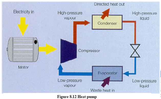
The heat pumps have the ability to upgrade heat to a value more than twice that of the energy consumed by the device. The potential for application of heat pump is growing and number of industries have been benefited by recovering low grade waste heat by upgrading it and using it in the main process stream.
Heat pump applications are most promising when both the heating and cooling capabilities can be used in combination. One such example of this is a plastics factory where chilled water from a heat is used to cool injection-moulding machines whilst the heat output from the heat pump is used to provide factory or office heating. Other examples of heat pump installation include product drying, maintaining dry atmosphere for storage and drying compressed air.
In many cases, very low pressure steam are reused as water after condensation for lack of any better option of reuse. In many cases it becomes feasible to compress this low pressure steam by very high pressure steam and reuse it as a medium pressure steam. The major energy in steam, is in its latent heat value and thus thermocompressing would give a large improvement in waste heat recovery.
The thermocompressor is a simple equipment with a nozzle where HP steam is accelerated into a high velocity fluid. This entrains the LP steam by momentum transfer and then recompresses in a divergent venturi. A figure of thermocompressor is shown in Figure 8.13.
It is typically used in evaporators where the boiling steam is recompressed and used as heating steam.
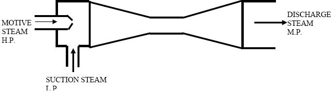
Figure 8.13 Thermocompressor
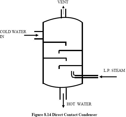
Low pressure steam may also be used to preheat the feed water or some other fluid where miscibility is acceptable. This principle is used in Direct Contact Heat Exchanger and finds wide use in a steam generating station. They essentially consists of a number of trays mounted one over the other or packed beds. Steam is supplied below the packing while the cold water is sprayed at the top. The steam is completely condensed in the incoming water thereby heating it. A figure of direct contact heat exchanger is shown in Figure 8.14. Typical application is in the deaerator of a steam generation station.