Based on the method of generating heat, furnaces are broadly classified into two types namely combustion type (using fuels) and electric type. In case of combustion type furnace, depending upon the kind of combustion, it can be broadly classified as oil fired, coal fired or gas fired.
Furnace should be designed so that in a given time, as much of material as possible can be heated to an uniform temperature as possible with the least possible fuel and labour. To achieve this end, the following parameters can be considered.
Since the products of flue gases directly contact the stock, type of fuel chosen is of importance. For example, some materials will not tolerate sulphur in the fuel. Also use of solid fuels will generate particulate matter, which will interfere the stock place inside the furnace. Hence, vast majority of the furnaces use liquid fuel, gaseous fuel or electricity as energy input.
Melting furnaces for steel, cast iron use electricity in induction and arc furnaces. Non-ferrous melting utilizes oil as fuel.
Furnace oil is the major fuel used in oil fired furnaces, especially for reheating and heat treatment of materials. LDO is used in furnaces where presence of sulphur is undesirable. The key to efficient furnace operation lies in complete combustion of fuel with minimum excess air.
Furnaces operate with efficiencies as low as 7% as against upto 90% achievable in other combustion equipment such as boiler. This is because of the high temperature at which the furnaces have to operate to meet the required demand. For example, a furnace heating the stock to 1200oC will have its exhaust gases leaving atleast at 1200oC resulting in a huge heat loss through the stack. However, improvements in efficiencies have been brought about by methods such as preheating of stock, preheating of combustion air and other waste heat recovery systems.
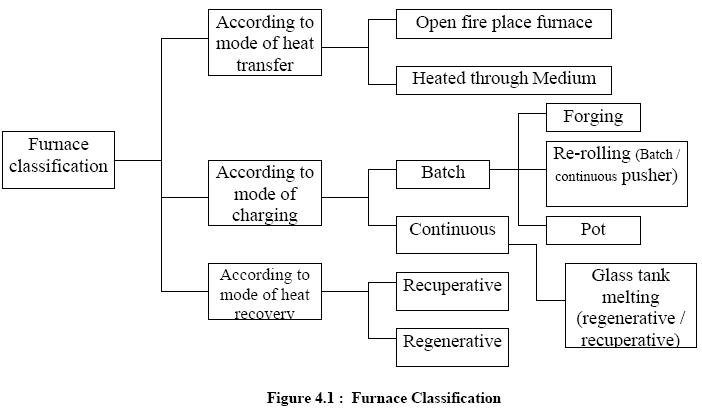
The forging furnace is used for preheating billets and ingots to attain a ‘forge’ temperature. The furnace temperature is maintained at around 1200 to 1250oC. Forging furnaces, use an open fireplace system and most of the heat is transmitted by radiation. The typical loading in a forging furnace is 5 to 6 tonnes with the furnace operating for 16 to 18 hours daily. The total operating cycle can be divided into (i) heat-up time (ii) soaking time and (iii) forging time. Specific fuel consumption depends upon the type of material and number of ‘reheats’ required.
a) Batch type
A box type furnace is employed for batch type rerolling mill. The furnace is basically used for heating up scrap, small ingots and billets weighing 2 to 20 kg. for rerolling. The charging and discharging of the ‘material’ is done manually and the final product is in the form of rods, strips etc. The operating temperature is about 1200 oC. The total cycle time can be further categorized into heat-up time and rerolling time. During heat-up time the material gets heated upto the required temperature and is removed manually for rerolling. The average output from these furnaces varies from 10 to 15 tonnes / day and the specific fuel consumption varies from 180 to 280 kg. of coal / tonne of heated material.
b) Continuous Pusher Type:
The process flow and operating cycles of a continuous pusher type is the same as that of the batch furnace. The operating temperature is about 1250 oC. Generally, these furnaces operate 8 to 10 hours with an output of 20 to 25 tonnes per day. The material or stock recovers a part of the heat in flue gases as it moves down the length of the furnace. Heat absorption by the material in the furnace is slow, steady and uniform throughout the cross-section compared with batch type.
iii) Continuous Steel Reheating Furnaces
The main function of a reheating furnace is to raise the temperature of a piece of steel, typically to between 900°C and 1250oC, until it is plastic enough to be pressed or rolled to the desired section, size or shape, The furnace must also meet specific requirements and objectives in terms of stock heating rates for metallurgical and productivity reasons. In continuous reheating, the steel stock forms a continuous flow of material and is heated to the desired temperature as it travels through the furnace.
All furnaces possess the features shown in Figure 4.2
The main ways in which heat is transferred to the steel in a reheating furnace are shown in Figure 4.3. In simple terms, heat is transferred to the stock by:
At the high temperatures employed in reheating furnaces, the dominant mode of heat transfer is wall radiation. Heat transfer by gas radiation is dependent on the gas composition (mainly the carbon dioxide and water vapour concentrations), the temperature and the geometry of the furnace.

Continuous reheating furnaces are primarily categorised by the method by which stock is transported through the furnace. There are two basic methods:
The major consideration with respect to furnace energy use is that the inlet and outlet apertures should be minimal in size and designed to avoid air infiltration.
i) Pusher Type Furnaces
The pusher type furnace is popular in steel industry. It has relatively low installation and maintenance costs compared to moving hearth furnaces. The furnace may have a solid hearth, but it is also possible to push the stock along skids with water-cooled supports that allow both the top and bottom faces of the stock to he heated. The design of a typical pusher furnace design is shown schematically in Figure 4.5.
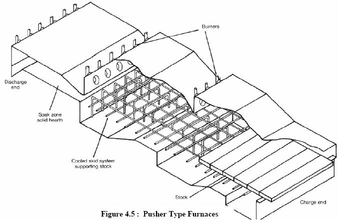
Pusher type furnaces, however, do have some disadvantages, including:
ii) Walking Hearth Furnaces
The walking hearth furnace (Figure.4.6) allows the stock to be transported through the furnace in discrete steps. Such furnaces have several attractive features, including: simplicity of design, ease of construction, ability to cater for different stock sizes (within limits), negligible water cooling energy losses and minimal physical marking of the stock.
The main disadvantage of walking hearth furnaces is that the bottom face of the stock cannot be heated. This can he alleviated to some extent by maintaining large spaces between pieces of stock. Small spaces between the individual stock pieces limits the heating of the side faces and increases the potential for unacceptable temperature differences within the stock at discharge. Consequently, the stock residence time may be long, possibly several hours; this may have an adverse effect on furnace flexibility and the yield may be affected by scaling.

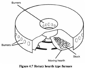
iii) Rotary hearth furnace
The rotary hearth furnace (Figure 4.7)has tended to supersede the recirculating bogie type. The heating and cooling effects introduced by the bogies are eliminated, so heat storage losses are less. The rotary hearth has, however a more complex design with an annular shape and revolving hearth.
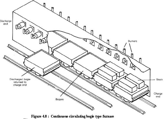
iv) Continuous Recirculating Bogie type Furnaces
These types of moving hearth type furnaces tend to be used for compact stock of variable size and geometry. In bogie furnaces (Figure 4.8), the stock is placed on a bogie with a refractory hearth, which travels through the furnace with others in the form of a train. The entire furnace length is always occupied by bogies. Bogie furnaces tend to be long and narrow and to suffer from problems arising from inadequate sealing of the gap between the bogies and furnace shell, difficulties in removing scale, and difficulties in firing across a narrow hearth width.
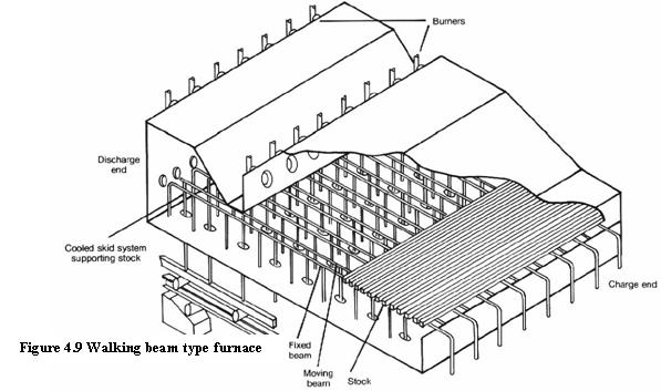
v) Walking Beam Furnaces
The walking beam furnace (Figure 4.9) overcomes many of the problems of pusher furnaces and permits heating of the bottom face of the stock. This allows shorter stock heating times and furnace lengths and thus better control of heating rates, uniform stock discharge temperatures and operational flexibility. In common with top and bottom fired pusher furnaces, however, much of the furnace is below the level of the mill; this may be a constraint in some applications.