There are three basic types of fluidised bed combustion boilers:
In AFBC, coal is crushed to a size of 1 – 10 mm depending on the rank of coal, type of fuel feed and fed into the combustion chamber. The atmospheric air, which acts as both the fluidization air and combustion air, is delivered at a pressure and flows through the bed after being preheated by the exhaust flue gases. The velocity of fluidising air is in the range of 1.2 to 3.7 m /sec. The rate at which air is blown through the bed determines the amount of fuel that can be reacted.
Almost all AFBC/ bubbling bed boilers use in-bed evaporator tubes in the bed of limestone, sand and fuel for extracting the heat from the bed to maintain the bed temperature. The bed depth is usually 0.9 m to 1.5 m deep and the pressure drop averages about 1 inch of water per inch of bed depth. Very little material leaves the bubbling bed – only about 2 to 4 kg of solids are recycled per ton of fuel burned. Typical fluidized bed combustors of this type are shown in Figures 6.3 and 6.4.

The combustion gases pass over the super heater sections of the boiler, flow past the economizer, the dust collectors and the air preheaters before being exhausted to atmosphere.
The main special feature of atmospheric fluidised bed combustion is the constraint imposed by the relatively narrow temperature range within which the bed must be operated. With coal, there is risk of clinker formation in the bed if the temperature exceeds 950oC and loss of combustion efficiency if the temperature falls below 800oC. For efficient sulphur retention, the temperature should be in the range of 800oC to 850oC.
AFBC boilers comprise of following systems:
Many of these are common to all types of FBC boilers
For feeding fuel, sorbents like limestone or dolomite, usually two methods are followed: under bed pneumatic feeding and over-bed feeding.
Under Bed Pneumatic Feeding
If the fuel is coal, it is crushed to 1-6 mm size and pneumatically transported from feed hopper to the combustor through a feed pipe piercing the distributor. Based on the capacity of the boiler, the number of feed points is increased, as it is necessary to distribute the fuel into the bed uniformly.
Over-Bed Feeding
The crushed coal, 6-10 mm size is conveyed from coal bunker to a spreader by a screw conveyor. The spreader distributes the coal over the surface of the bed uniformly. This type of fuel feeding system accepts over size fuel also and eliminates transport lines, when compared to under-bed feeding system.
The purpose of the distributor is to introduce the fluidizing air evenly through the bed cross section thereby keeping the solid particles in constant motion, and preventing the formation of defluidization zones within the bed. The distributor, which forms the furnace floor, is normally constructed from metal plate with a number of perforations in a definite geometric pattern. The perforations may be located in simple nozzles or nozzles with bubble caps, which serve to prevent solid particles from flowing back into the space below the distributor.
The distributor plate is protected from high temperature of the furnace by:
a) Bed
The bed material can be sand, ash, crushed refractory or limestone, with an average size of about 1 mm. Depending on the bed height these are of two types: shallow bed and deep bed.
At the same fluidizing velocity, the two ends fluidise differently, thus affecting the heat transfer to an immersed heat transfer surfaces. A shallow bed offers a lower bed resistance and hence a lower pressure drop and lower fan power consumption. In the case of deep bed, the pressure drop is more and this increases the effective gas velocity and also the fan power.
b) In-Bed Heat Transfer Surface
In a fluidized in-bed heat transfer process, it is necessary to transfer heat between the bed material and an immersed surface, which could be that of a tube bundle, or a coil. The heat exchanger orientation can be horizontal, vertical or inclined. From a pressure drop point of view, a horizontal bundle in a shallow bed is more attractive than a vertical bundle in a deep bed. Also, the heat transfer in the bed depends on number of parameters like (i) bed pressure (ii) bed temperature (iii) superficial gas velocity (iv) particle size (v) Heat exchanger design and (vi) gas distributor plate design.
a) Bottom ash removal
In the FBC boilers, the bottom ash constitutes roughly 30 - 40 % of the total ash, the rest being the fly ash. The bed ash is removed by continuous over flow to maintain bed height and also by intermittent flow from the bottom to remove over size particles, avoid accumulation and consequent defluidization. While firing high ash coal such as washery rejects, the bed ash overflow drain quantity is considerable so special care has to be taken.
b) Fly ash removal
The amount of fly ash to be handled in FBC boiler is relatively very high, when compared to conventional boilers. This is due to elutriation of particles at high velocities. Fly ash carried away by the flue gas is removed in number of stages; firstly in convection section, then from the bottom of air preheater/economizer and finally a major portion is removed in dust collectors.
The types of dust collectors used are cyclone, bagfilters, electrostatic precipitators (ESP’s) or some combination of all of these. To increase the combustion efficiency, recycling of fly ash is practiced in some of the units.
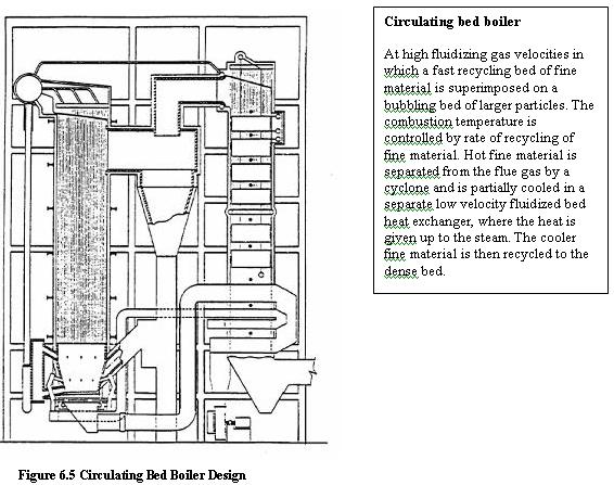
Circulating Fluidised Bed Combustion (CFBC) technology has evolved from conventional bubbling bed combustion as a means to overcome some of the drawbacks associated with conventional bubbling bed combustion (see Figure 6.5).
This CFBC technology utilizes the fluidized bed principle in which crushed (6 –12 mm size) fuel and limestone are injected into the furnace or combustor. The particles are suspended in a stream of upwardly flowing air (60-70% of the total air), which enters the bottom of the furnace through air distribution nozzles. The fluidising velocity in circulating beds ranges from 3.7 to 9 m/sec. The balance of combustion air is admitted above the bottom of the furnace as secondary air. The combustion takes place at 840- 900oC, and the fine particles (450 microns) are elutriated out of the furnace with flue gas velocity of 4-6 m/s. The particles are then collected by the solids separators and circulated back into the furnace. Solid recycle is about 50 to 100 kg per kg of fuel burnt.
There are no steam generation tubes immersed in the bed. The circulating bed is designed to move a lot more solids out of the furnace area and to achieve most of the heat transfer outside the combustion zone - convection section, water walls, and at the exit of the riser. Some circulating bed units even have external heat exchanges. The particles circulation provides efficient heat transfer to the furnace walls and longer residence time for carbon and limestone utilization. Similar to Pulverized Coal (PC) firing, the controlling parameters in the CFB combustion process are temperature, residence time and turbulence.
For large units, the taller furnace characteristics of CFBC boiler offers better space utilization, greater fuel particle and sorbent residence time for efficient combustion and SO2 capture, and easier application of staged combustion techniques for NOx control than AFBC generators. CFBC boilers are said to achieve better calcium to sulphur utilization – 1.5 to 1 vs. 3.2 to 1 for the AFBC boilers, although the furnace temperatures are almost the same.
CFBC boilers are generally claimed to be more economical than AFBC boilers for industrial application requiring more than 75 – 100 T/hr of steam
CFBC requires huge mechanical cyclones to capture and recycle the large amount of bed material, which requires a tall boiler.
A CFBC could be good choice if the following conditions are met.
Major performance features of the circulating bed system are as follows:
Pressurised Fluidised Bed Combustion (PFBC) is a variation of fluid bed technology that is meant for large-scale coal burning applications. In PFBC, the bed vessel is operated at pressure upto 16 ata ( 16 kg/cm2).
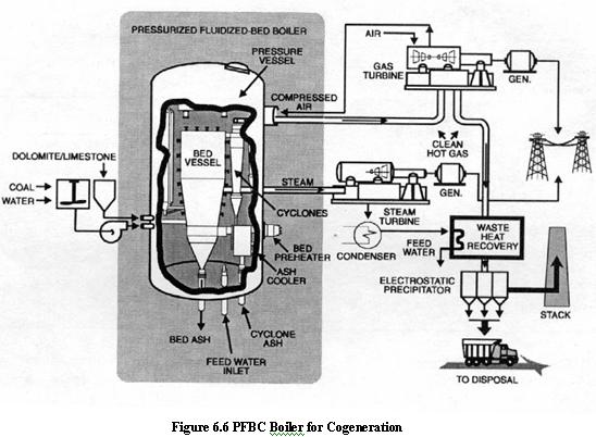
The off-gas from the fluidized bed combustor drives the gas turbine. The steam turbine is driven by steam raised in tubes immersed in the fluidized bed. The condensate from the steam turbine is pre-heated using waste heat from gas turbine exhaust and is then taken as feed water for steam generation.
The PFBC system can be used for cogeneration or combined cycle power generation. By combining the gas and steam turbines in this way, electricity is generated more efficiently than in conventional system. The overall conversion efficiency is higher by 5% to 8%. . (Refer Figure 6.6).
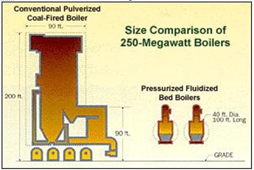
At elevated pressure, the potential reduction in boiler size is considerable due to increased amount of combustion in pressurized mode and high heat flux through in-bed tubes. A comparison of size of a typical 250 MW PFBC boiler versus conventional pulverized fuel-fired boiler is shown in the Figure 6.7.