
Typical energy efficiency measures for an industry with furnace are:
The amount of heat lost in the flue gases (stack losses) depends upon amount of excess air. In the case of a furnace carrying away flue gases at 900oC, % heat lost is shown in table 4.3:
To obtain complete combustion of fuel with the minimum amount of air, it is necessary to control air infiltration, maintain pressure of combustion air, fuel quality and excess air monitoring.
Higher excess air will reduce flame temperature, furnace temperature and heating rate. On the other hand, if the excess air is less, then unburnt components in flue gases will increase and would be carried away in the flue gases through stack. The figure 4.16 also indicates relation between air ratio and exhaust gas loss.
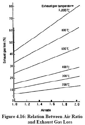
The optimization of combustion air is the most attractive and economical measure for energy conservation. The impact of this measure is higher when the temperature of furnace is high. Air ratio is the value that is given by dividing the actual air amount by the theoretical combustion air amount, and it represents the extent of excess of air.
If a reheating furnace is not equipped with an automatic air/fuel ratio controller, it is necessary to periodically sample gas in the furnace and measure its oxygen contents by a gas analyzer. The Figure 4.17 shows a typical example of a reheating furnace equipped with an automatic air/fuel ratio controller.

More excess air also means more scale losses, which is equally a big loss in terms of money.
Furnace design should be such that in a given time, as much of the stock could be heated uniformly to a desired temperature with minimum fuel firing rate.
Following care should be taken when using burners, for proper heat distribution:

It is important to operate the furnace at optimum temperature. The operating temperatures of various furnaces are given in Table 4.4.

Operating at too high temperatures than optimum causes heat loss, excessive oxidation, de-carbonization as well as over-stressing of the refractories. These controls are normally left to operator judgment, which is not desirable. To avoid human error, on/off controls should be provided.
Heat loss through openings consists of the heat loss by direct radiation through openings and the heat loss caused by combustion gas that leaks through openings.
The heat loss from an opening can also be calculated using the following formula:

where
T: absolute temperature (K)
a: factor for total radiation
A: area of opening, m2
H: time (Hr)
This is explained by an example as follows.
A reheating furnace with walls 460 mm thick (X) has a billet extraction outlet, which is 1 m high (D) and 1 m wide. When the furnace temperature is 1,340°C the quantity (Q) of radiation heat loss from this opening is evaluated as follows.
The shape of opening is square, and D/X = l/0.46 = 2.17. Thus, the factor for total radiation is 0.71 (refer Figure 4.3) and we get

If the furnace pressure is slightly higher than outside air pressure (as in case of reheating furnace) during its operation, the combustion gas inside may blow off through openings and heat is lost with that. But damage is more, if outside air intrudes into the furnace, making temperature distribution uneven and oxidizing billets. This heat loss is about 1% of the total quantity of heat generated in the furnace, if furnace pressure is controlled properly.
negative pressures exist in the furnace, air infiltration is liable to occur through the cracks and openings thereby affecting air-fuel ratio control. Tests conducted on apparently airtight furnaces have shown air infiltration up to the extent of 40%. Neglecting furnaces pressure could mean problems of cold metal and non-uniform metal temperatures, which could affect subsequent operations like forging and rolling and result in increased fuel consumption. For optimum fuel consumption, slight positive pressure should be maintained in the furnace as shown in Figure 4.20.

Ex-filtration is less serious than infiltration. Some of the associated problems with ex filtration are leaping out of flames, overheating of the furnace refractories leading to reduced brick life, increased furnace maintenance, burning out of ducts and equipments attached to the furnace, etc.
In addition to the proper control on furnace pressure, it is important to keep the openings as small as possible and to seal them in order to prevent the release of high temperature gas and intrusion of outside air through openings such as the charging inlet, extracting outlet and peephole on furnace walls or the ceiling.
One of the most vital factors affecting efficiency is loading. There is a particular loading at which the furnace will operate at maximum thermal efficiency. If the furnace is under loaded a smaller fraction of the available heat in the working chamber will be taken up by the load and therefore efficiency will be low.
The best method of loading is generally obtained by trial-noting the weight of material put in at each charge, the time it takes to reach temperature and the amount of fuel used. Every endeavour should be made to load a furnace at the rate associated with optimum efficiency although it must be realised that limitations to achieving this are sometimes imposed by work availability or other factors beyond control.
The loading of the charge on the furnace hearth should be arranged so that
Stock should not be placed in the following position
The other reason for not operating the furnace at optimum loading is the mismatching of furnace dimension with respect to charge and production schedule.
In the interests of economy and work quality the materials comprising the load should only remain in the furnace for the minimum time to obtain the required physical and metallurgical requirements. When the materials attain these properties they should be removed from the furnace to avoid damage and fuel wastage. The higher the working temperature, higher is the loss per unit time. The effect on the materials by excessive residence time will be an increase in surface defects due to oxidation. The rate of oxidation is dependent upon time, temperature, as well as free oxygen content. The possible increase in surface defects can lead to rejection of the product. It is therefore essential that coordination between the furnace operator, production and planning personnel be maintained.
Optimum utilization of furnace can be planned at design stage. Correct furnace for the jobs should be selected considering whether continuous or batch type furnace would be more suitable. For a continuous type furnace, the overall efficiency will increase with heat recuperation from the waste gas stream. If only batch type furnace is used, careful planning of the loads is important. Furnace should be recharged as soon as possible to enable use of residual furnace heat.
In any industrial furnace the products of combustion leave the furnace at a temperature higher than the stock temperature. Sensible heat losses in the flue gases, while leaving the chimney, carry 35 to 55 per cent of the heat input to the furnace. The higher the quantum of excess air and flue gas temperature, the higher would be the waste heat availability.
Waste heat recovery should be considered after all other energy conservation measures have been taken. Minimizing the generation of waste heat should be the primary objective.
The sensible heat in flue gases can be generally recovered by the following methods. (Figure 4.21)

Charge Pre-heating
When raw materials are preheated by exhaust gases before being placed in a heating furnace, the amount of fuel necessary to heat them in the furnace is reduced. Since raw materials are usually at room temperature, they can be heated sufficiently using high- temperature gas to reduce fuel consumption rate.
Preheating of Combustion Air
For a long time, the preheating of combustion air using heat from exhaust gas was not used except for large boilers, metal-heating furnaces and high-temperature kilns. This method is now being employed in compact boilers and compact industrial furnaces as well. (Refer Figure 4.22)

The energy contained in the exhaust gases can be recycled by using it to pre-heat the combustion air. A variety of equipment is available; external recuperators are common, but other techniques are now available such as self-recuperative burners. For example, with a furnace exhaust gas temperature of l,000°C, a modern recuperator can pre-heat the combustion air to over 500"C, giving energy savings compared with cold air of up to 30%
External Recuperators
There are two main types of external recuperators
Radiation recuperators generally take the form of concentric cylinders, in which the combustion air passes through the annulus and the exhaust gases from the furnace pass through the centre, see Fig 23(a). The simple construction means that such recuperators are suitable for use with dirty gases, have a negligible resistance to flow, and can replace the flue or chimney if space is limited. The annulus can be replaced by a ring of vertical tubes, but this design is more difficult to install and maintain. Radiation recuperators rely on radiation from high temperature exhaust gases and should not he employed with exhaust gases at less than about 800°C.
Convection recuperators consist essentially of bundles of drawn or cast tubes, see Fig 23(b). Internal and/or external fins can be added to assist heat transfer. The combustion air normally passes through the tubes and the exhaust gases outside the tubes, but there are some applications where this is reversed. For example, with dirty gases, it is easier to keep the tubes clean if the air flows on the outside. Design variations include ‘U’ tube and double pass systems. Convection recuperators are more suitable for exhaust gas temperatures of less than about 900°C.

Self Recuperative Burners
Self-recuperative burners (SRBs) are based on traditional heat recovery techniques in that the products of combustion are drawn through a concentric tube recuperator around the burner body and used to pre-heat the combustion air (Figure 24.)

A major advantage of this type of system is that it can be retro-fitted to an existing furnace structure to increase production capability without having to alter the existing exhaust gas ducting arrangements. SRBs are generally more suited to heat treatment furnaces where exhaust gas temperatures are lower and there are no stock recuperation facilities.
Estimation of fuel savings
By using preheated air for combustion, fuel can be saved. The fuel saving rate is given by the following formula:

where
S: fuel saving rate, %
F: Calorific value of fuel (kCal/kg fuel)
P: quantity of heat brought in by preheated air (kCal/kg fuel
Q: quantity of heat taken away by exhaust gas (kCal/kg fuel)
By this formula, fuel saving rates for heavy oil and natural gas were calculated for various temperatures of exhaust gas and preheated air. The results are shown in the following Figure 4.25 and Figure 4.26.


For example, when combustion air for heavy oil is preheated to 400°C by a heat exchanger with an inlet temperature of 800 °C, the fuel conservation rate is estimated to be about 20 percent. When installing a recuperator in a continuous steel reheating furnace, it is important to choose a preheated air temperature that will balance the fuel saving effect and the invested cost for the equipment.
Also, the following points should be checked:
Since the volume of air is increased owing to its preheating, it is necessary to be careful about the modification of air-duct diameters and blowers. As for the use of combustion gases resulting from high-density oils with a high sulphur content, care must be taken to avoid problems such as clogging with dust or sulphides, corrosion or increases in nitrogen oxides.
Utilizing Waste Heat as a Heat Source for Other Processes
The temperature of heating-furnace exhaust gas can be as high as 400- 600 °C, even after heat has been recovered from it.
When a large amount of steam or hot water is needed in a plant, installing a waste heat boiler to produce the steam or hot water using the exhaust gas heat is preferred. If the exhaust gas heat is suitable for equipment in terms of heat quantity, temperature range, operation time etc., the fuel consumption can be greatly reduced. In one case, exhaust gas from a quenching furnace was used as a heat source in a tempering furnace so as to obviate the need to use fuel for the tempering furnace itself.
About 30-40% of the fuel input to the furnace generally goes to make up for heat losses in intermittent or continuous furnaces. The appropriate choice of refractory and insulation materials goes a long way in achieving fairly high fuel savings in industrial furnaces.
The heat losses from furnace walls affect the fuel economy considerably. The extent of wall losses depend on:
Heat losses can be reduced by increasing the wall thickness, or through the application of insulating bricks. Outside wall temperatures and heat losses of a composite wall of a certain thickness of firebrick and insulation brick are much lower, due to lesser conductivity of insulating brick as compared to a refractory brick of similar thickness. In the actual operation in most of the small furnaces the operating periods alternate with the idle periods. During the off period, the heat stored in the refractories during the on period is gradually dissipated, mainly through radiation and convection from the cold face. In addition, some heat is abstracted by air flowing through the furnace. Dissipation of stored heat is a loss, because the lost heat is again imparted to the refractories during the heat “on” period, thus consuming extra fuel to generate that heat. If a furnace is operated 24 hours, every third day, practically all the heat stored in the refractories is lost. But if the furnace is operated 8 hours per day all the heat stored in the refractories is not dissipated. For a furnace with a firebrick wall of 350 mm thickness, it is estimated that 55 percent of the heat stored in the refractories is dissipated from the cold surface during the 16 hours idle period. Furnace walls built of insulating refractories and cased in a shell reduce the flow of heat to the surroundings.
Prevention of Radiation Heat Loss from Surface of Furnace
The quantity of heat release from surface of furnace body is the sum of natural convection and thermal radiation. This quantity can be calculated from surface temperatures of furnace. The temperatures on furnace surface should be measured at as many points as possible, and their average should be used. If the number of measuring points is too small, the error becomes large.
The quantity (Q) of heat release from a reheating furnace is calculated with the following formula:

where
Q: Quantity of heat released (kCal/hr)
a : factor regarding direction of the surface of natural convection ceiling = 2.8, side walls = 2.2, hearth = 1.5
tl : temperature of external wall surface of the furnace (°C)
t2 : temperature of air around the furnace (°C)
E: emissivity of external wall surface of the furnace
The first term of the formula above represents the quantity of heat release by natural convection, and the second term represents the quantity of heat release by radiation. The following Figure 4.27 shows the relation between the temperature of external wall surface and the quantity of heat release calculated with this formula.

This is explained with an example as follows:
There is a reheating furnace whose ceiling; side walls and hearth have 20 m2, 50 m2 and 20 m2 of surface area respectively. Their surface temperatures are measured, and the averages are 80°C, 90°C and 100°C respectively. Evaluate the quantity of heat release from the whole surface of this furnace.
From the above Figure 4.26, the quantities of heat release from ceiling, side walls and hearth per unit area are respectively 650 kCal/m2h , 720 kCal/m2h and 730 kCal/m2h.
Therefore, the total quantity of heat release is
Q = 650x20+720x50+730x20
= 13000 + 36000 +14600= 63,600 kCal/hr
Use of Ceramic Fibre
Ceramic fibre is a low thermal mass refractory used in the hot face of the furnace and fastened to the refractory walls. Due to its low thermal mass the storage losses are minimized. This results in faster heating up of furnace and also faster cooling. Energy savings by this application is possible only in intermittent furnaces. More details about ceramic fibre are given in the chapter on insulation and refractories.
Ceramic coatings in furnace chamber promote rapid and efficient transfer of heat, uniform heating and extended life of refractories. The emissivity of conventional refractories decreases with increase in temperature whereas for ceramic coatings it increases. This outstanding property has been exploited for use in hot face insulation.
Ceramic coatings are high emissivity coatings which when applied has a long life at temperatures up to 1350oC. The coatings fall into two general categories-those used for coating metal substrates, and those used for coating refractory substrates. The coatings are non-toxic, non-flammable and water based. Applied at room temperatures, they are sprayed and air dried in less than five minutes. The coatings allow the substrate to maintain its designed metallurgical properties and mechanical strength. Installation is quick and can be completed during shut down. Energy savings of the order of 8-20% have been reported depending on the type of furnace and operating conditions.
All the possible measures discussed can be incorporated in furnace design and operation. The figure 4.28 shows characteristics diagram of energy conservation for a fuel-fired furnace.
